It is well-known that for equipment and components design that will be operated in industrial plants, all involved people must take into account all phenomena that could cause failures. The main reason for that is people safety and integrity that work at the plant and all people that could be affected by a hypothetical failure. To a lesser extent, but considering a high relevance, economic subject derived from repairs, equipment and components changes and plant shut-down should be considered.
One of the most harmful types of failure that we could find in industrial plantss what is commonly named as Creep. It consists of time-dependent strain of a material, considering a constant stress and a high temperature. This definition allow us to establish an important warning that is useful for any involved agent in development of industrial plants and their components: when high temperatures, high stresses and a sufficiently long period of time are concomitants, we must take into account the potential impact of creep effect in material that is subjected to it.
That being said, it is convenient to clarify what high temperatures, high stress and long period of time mean. Applicable temperature which this phenomenon appears depends of, among other variables, material alloy. In addition to previous sentence and in order to have a guideline, it could be said that a temperature slightly higher than the recrystallization one could be considered as a creep start. If material has achieved this recrystallization temperature, its atoms are mobile enough to permit material structure reordering. In general, in applicable codes and standards for design and analysis of components in industrial sector the user could find a criterion about when creep starts. ASME Section II Part D can be considered as an example about this, because of this code establish a time-dependent temperature for each material. As it has mentioned above, when user has to be worried because of creep and when user can discard this phenomenon could be determined only if all applicable variables (temperature, stress, time and material alloy) have been analyzed.
Taking into account metallurgical topics, this phenomenon usually could be attributed to vacancy migration in grains of bulk materials or along the material grain boundaries in the same direction of applied stress, and causing grain boundary sliding and separation [1].

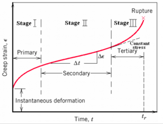
As it shown in above figure, the creep effect, plotted in a time-strain curve regarding a constant load, could be divided in three different stages and all of them are summarily explained as follows.
- Primary creep: at this first stage, a hardening transient occurs and the creep rate decreases up to reaching a steady state one.
- Secondary creep: at this second stage the creep rate achieves a steady state. This curve portion is almost predictable and linear and it is the most important part to involved engineer.
- Tertiary creep: at this final stage, creep rate increases quickly by means a sudden strain and results in final rupture of the material.
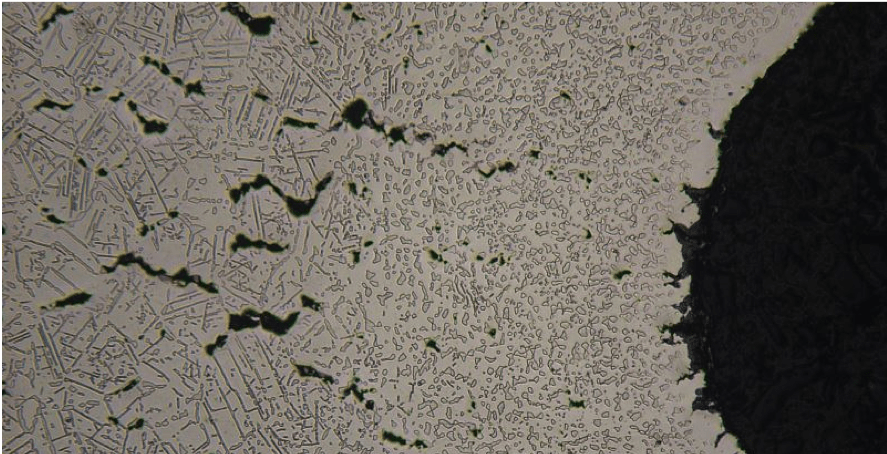
Just as a comment, we should note that the first microstructural evidence of creep presence does not appear neither in first stage nor in second one. That evidence consists of individual voids or pores. When those cavities grow and come together, it forms cracks. Finally, material failure happens.
Once the problem has been exposed, how to resolve it is totally necessary in order to have creep effects under control during the component entire operating life. There are several codes and standards that establish procedure and criteria for calculating of remaining life of a specific component that is submitted to creep phenomenon. Users of API 579/ASME FFS-1, EN 13445 or API 530, could find all necessary information addressing this phenomenon there. Needless to say that for using these procedures to have a detailed knowledge about components operating conditions and external load that affects to it is necessary.
If the results of the calculation indicates that the analyzed component will have further problems derived from creep effect, we should modify values or magnitudes of variables that impact in this phenomenon if we want to avoid dangerous consequences. Just as a guideline, external loads should be reduced, operating temperature could be decreased, component time in service should be limited or a higher material grain size could be achieved.
Last but not least, we should focus that creep could not be the only harmful effect that affects to component during its entire operating life, and other effects could appear and their combination with creep involves a particularly dangerous result. It should be noted creep-fatigue as a especially important combination.
[1] Faridani, M. N.; “Classification and probabilistic model development for creep failures of structures: Study of X-70 carbon steel and 7075-T6 Aluminum Alloys”. 2011.
If you want to know more:
ASME VIII | Design of Pressure Vessels
TEMA | Design of Shell & Tube Heat Exchangers


 WhatsApp