Thermal expansion effects in static equipment
- Posted by: César Boró Martín
- Category: Static Equipment

Nowadays, in many types of industrial plants, there are pressure vessels in service that work at temperatures that could be considered as severe, either low (cryogenic) or, conversely, high temperature. One of the main problems that needs to be addressed is the interaction with the support components of these equipment, that is, foundations or supporting structures. The features of these elements will be subjected to the applicable temperature, therefore, the temperature transmitted by the pressure vessel should be under control in order to avoid damaging the supporting elements.
The foundation or supporting structure designer engineer must determine the maximum allowable temperature for the different components. Based on this input, several pressure vessel elements must be designed, e.g. skirt, legs, support lugs, and their insulation characteristics. Often, it is necessary to install and additional component between the pressure vessel and the foundation, or as an integrant part of the foundation. The purpose of this component is to break the thermal bridge, i.e. to prevent extreme temperatures being transmitted to the foundation.
The calculation and the design of this intermediate component must consider both the thermal characteristics of the assembly, as well as the mechanical ones, since it could have to withstand compression or shear loads. One of the most widely used materials in this kind of applications is the mica, because of its good quality as an insulation material and its high strength to compression loads (not to shear loads).

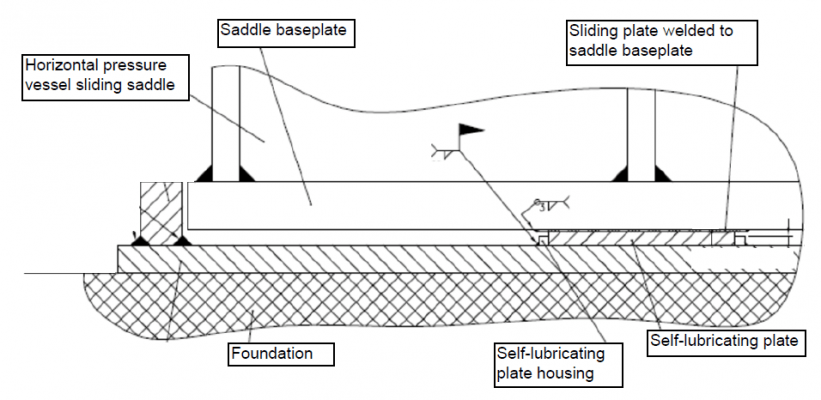
At the same time, these effects should be also considered in the pressure vessel. Two important issues have to be considered. The first one is to be aware that an equipment that expands or contracts will tend to develop a relative movement in relation to the foundation and this effect will involve stresses that should be minimized as much as possible, especially if the pressure vessel is subjected to thermal fatigue. For that, the most appropriate method is not to restrict the expansion and contraction movements, due to the stresses that both elements, equipment and foundation, will have to withstand are reduced. In order to permit those movements, elements that are located in the interface between vessel and foundation and that reduce the friction coefficient are usually used. The material chosen and the configuration of these elements are dependent on the specific features of the equipment being studied. For instance, elements that are made of teflon, graphite-bronze or, even, paint-coatings are commonly installed for these applications.
The second topic that should be considered is that an equipment involved in this kind of services, will have to withstand an operating temperature quite high or low, which will be transferred to the adjacent components, that in turn will induce thermal stresses in the vessel. Because of this effect, the design of the interface between foundation and the pressure vessel must guarantee that the stress level is higher than the allowable. In these cases, it is necessary to arrive to a compromise solution in order to satisfy the needs of both components. If the thermal energy dissipation is high along the equipment supports (i.e. skirt, saddles, support lugs), it means a better foundation behaviour but, therefore, it means a higher thermal gradient in the equipment, with consequent higher thermal stresses.
Regarding vertical pressure vessels supported on skirt and with a high operating temperature, it is quite usual to implement a solution named as hot box (350ºC could be considered as a minimum temperature to use this device), which consists of an insulation-free space in the inside part of the equipment, located in the joint skirt-bottom head, to minimize the stresses discontinuity in this zone, what is achieved by means of a reduced thermal gradient.
A common way to develop the design and calculation of thermal breaker elements, pressure vessel supporting elements (e.g. skirt, legs) and their thermal gradients is using a finite elements model. This involves a very complex analysis; firstly the designer will have to establish the calculation inputs (e.g. wind speed, the temperature of air surrounding the equipment, assembly components thermomechanical properties) with a realistic criterion and, during the calculation development, input values must be managed in a precise way (e.g. film coefficient calculation) in order to avoid a non-realistic scenario.
If you want to know more:


 WhatsApp