


In shell and tube heat exchangers, fouling is one of the most frequent causes of thermal performance loss during operation. It consists of the progressive accumulation of unwanted deposits on heat transfer surfaces. These deposits add thermal resistance and reduce the flow area, which increases pressure drop.
The consequences are both technical and economic: higher energy consumption, cleaning shutdowns, design oversizing and, in some cases, under-deposit corrosion. Understanding the mechanisms that cause it is the first step toward preventing it with sound engineering judgment.
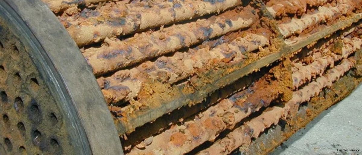
Fouling and Its Effect on Design
The thermal effect of fouling is included in calculations through the fouling resistance (R_f), which is added to the other resistances in the overall heat transfer coefficient (U). It is usually expressed in m²·K/W or h·ft²·°F/Btu. The TEMA standard provides indicative R_f values by fluid type in its recommended good practice section.
These values are a reference and do not replace experience with the specific service. An underestimated R_f leads to premature loss of capacity. An overestimated one results in excess surface area, which may operate at lower-than-optimal velocities, and this in turn may promote fouling.
Fouling Mechanisms
The technical literature distinguishes six main mechanisms. They can act simultaneously and reinforce one another.
- Crystallization fouling (scaling). It occurs when dissolved salts exceed their solubility limit and precipitate on the surface. It is characteristic of cooling water with inverse-solubility salts, such as calcium carbonate, whose solubility decreases as temperature rises. Hot wall zones are therefore the most exposed.
- Particulate fouling (sedimentation). Suspended solids, such as sand, corrosion products, or process fines, settle in low-velocity zones. They accumulate especially on the shell side, in dead zones between baffles, and in channel passes.
- Chemical reaction fouling. Reactions within the process fluid itself, often temperature-dependent, generate low-solubility products that adhere to the wall. Typical examples are polymerization, coke formation, and thermal degradation of hydrocarbons. In crude preheat trains, a well-documented relationship exists between film temperature and deposition rate.
- Corrosion fouling. The metal surface itself reacts with the fluid and generates adherent corrosion products. These deposits can reduce heat transfer and, in turn, promote particle retention.
- Biological fouling. Microorganisms and macroorganisms colonize surfaces, forming biofilms. It is typical of cooling water circuits, especially with seawater or river water, at moderate temperature ranges.
- Solidification fouling. A fluid, or one of its components, solidifies on a cold surface. It occurs, for example, with waxes or paraffins when the wall temperature falls below their crystallization point.
Evolution over time
The process is usually described in stages: induction, transport of the species to the wall, attachment, partial removal by shear stress, and deposit aging. In certain regimes, when deposition and removal reach equilibrium, the resistance tends toward an asymptotic value. In others, growth is continuous, with sloughing or non-monotonic evolution. In any case, the expected cleaning frequency must be anticipated from the design stage.
Prevention at the Design Stage
Most effective measures are decided during design. The most relevant are:
- Fluid allocation. The dirtier fluid should generally be placed on the tube side, where mechanical cleaning is simpler, unless other considerations (pressure, corrosion, pressure drop) advise otherwise.
- Construction type selection. For severe shell-side fouling, removable bundles (floating head) allow complete mechanical cleaning. Fixed tubesheets limit accessibility for mechanical cleaning of the shell side, so they may require chemical cleaning or other techniques compatible with the configuration. In U-tube designs, internal mechanical cleaning is more complicated, which makes it inadvisable to place the fouling fluid on the tube side.
- Fluid velocity. In general, higher velocities increase wall shear stress and favor deposit removal. However, the effect depends on the dominant mechanism and on the balance between transport, attachment, and removal. In corrosion fouling, for example, high velocity can increase the transport of species to the wall or damage protective layers. The upper limit is set by erosion and pressure drop. It must also be verified that the unit does not operate at low velocities under turndown conditions.
- Wall temperature. Surface or film temperature should be limited in services where crystallization or chemical reaction fouling depends on it. Heating with excessive temperature differences can be counterproductive.
- Bundle layout and baffles. A square pitch, either 90° or rotated 45°, potentially facilitates mechanical cleaning between tubes, provided that cleaning lanes, clearances, and effective access to the surfaces are verified. Dead zones and recirculation areas where solids accumulate should be avoided, and TEMA criteria on spacing should be taken into account.
- Materials and surface finish. Selecting corrosion-resistant materials reduces corrosion fouling and the formation of rough surfaces that promote adhesion.
Prevention in Operation
Once in service, prevention relies on controlling process conditions:
- Filtration and fluid treatment to reduce suspended solids upstream of the exchanger.
- Chemical treatment, using dispersants, scale and corrosion inhibitors, and biocides in cooling water circuits.
- Maintaining flow rates and temperatures within the design range, avoiding start-ups and shutdowns that leave stagnant product in the unit.
- Control of cooling water conditions, such as pH, hardness, and cycles of concentration.
Monitoring and Cleaning
Tracking actual fouling makes it possible to schedule cleaning before performance drops below a critical threshold. The most common indicators are:
- The evolution of the overall heat transfer coefficient (U) or the fouling resistance R_f. The latter is not measured directly: it is inferred from a heat balance and a reference model, and must be normalized against actual flow and temperature conditions before attributing its variations to fouling.
- The pressure drop increase on the affected side.
- The deviation of outlet temperatures from design values.
Cleaning can be mechanical (high-pressure hydroblasting, lances, or rotary tools) or chemical (circulation of solutions suited to the deposit type). The choice must consider the nature of the deposit, equipment materials, and accessibility, which is established at the design stage.
Frequent Errors
- Adopting tabulated R_f values without contrasting them with experience from the actual service.
- Compensating for expected fouling solely with additional surface area, which lowers velocities and may aggravate it.
- Selecting fixed tubesheets in services with severe shell-side fouling.
- Not providing access and space for bundle extraction and cleaning.
- Operating for prolonged periods at flow rates well below design.
- Not monitoring U or pressure drop, and cleaning only when the unit no longer meets duty.
Conclusion
Fouling is not a single phenomenon but the result of several physical, chemical, and biological mechanisms that depend on the fluid, wall temperature, and equipment hydrodynamics. Managing it effectively combines a design that considers velocity, wall temperature, TEMA construction type, and cleaning accessibility from the outset with controlled operation and systematic monitoring. This reduces the impact on energy cost, availability, and exchanger lifecycle.
 WhatsApp