
Transportation loads on mechanical equipment
In the design of mechanical equipment, especially large static and rotating equipment, it is essential to carry out a detailed design and analysis of the stresses generated due to the loads induced during the transportation on the different elements of the equipment.
If we analyze, for example, the case of a pressure vessel, the transportation of this equipment will generate stresses both in the shell and in the saddles, which must have been foreseen during the design phase to avoid possible failures during the transportation.
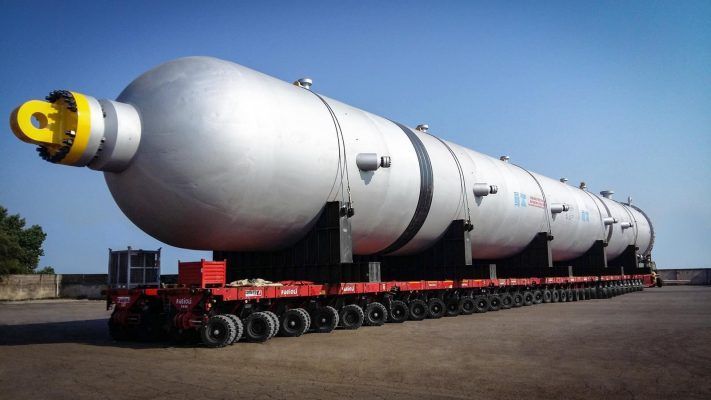
In general, vertical equipment are designed to be transported supported on two saddles, generally made of steel, although saddles made of other materials such as wood can also be used. Special attention should be paidto vertical equipment with long lengths and small thicknesses. Generally, horizontal equipment are transported on its own saddles, so the conditions generated during transport must be considered during the design phase.
A good communication between the different affected departments (static equipment, logistics, and construction) is essential in order to define the supports, location, lashing points, as well as the saddle length, in order to facilitate their unloading and future operations on site, such as their pre-dressed activities, minimizing the subcontracting of special cranes as much as possible.
The logistics department should carry out an analysis of the different routes, in order to analyze possible obstacles or restrictions during transport, ensuring its viability and cost optimization. In this line, in order to avoid delays and incur in possible penalties, it is essential to make sure that all necessary permits are valid and up to date, following local and international regulations.
There are different ways of transporting mechanical equipment. Depending on the geographical location of the Vendor’s shop and the location of the plant, one method will be chosen. The most used means of transport for mechanical equipment are the following:
– Road Transportation
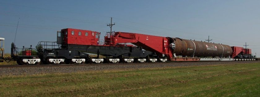
– Rail Transportation
– Ship/barge Transportation
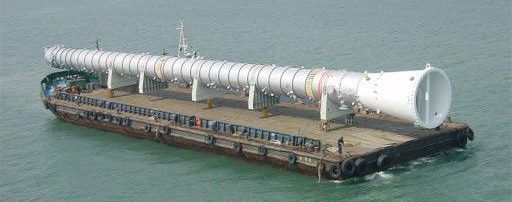
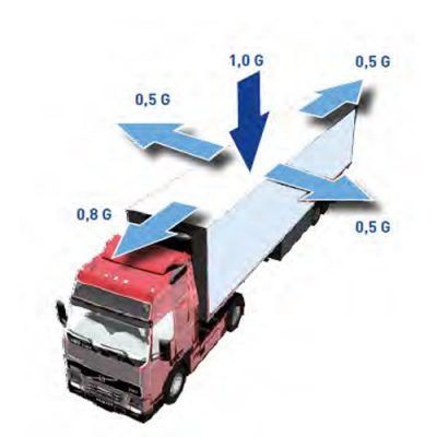
Depending on the selected method, mechanical equipment will be subject to accelerations on the three main axes; longitudinal, transverse, and vertical, which must be analyzed. In the case of maritime transport, these accelerations will depend on the type of ship and the location of the equipment on the ship as well as the conditions of the sea or ocean (maximum waves) through which the transport is carried out.
The designer of the equipment should be able to transfer the resulting loads generated during transportation into loads applied to the equipment, generally, these loads are defined as spectral acceleration values.
As early in the process as possible, the ship/barge contractor shall indicate to the equipment designer the estimated acceleration values during the transportation to be considered during the design, in order to optimize the equipment configuration, and to reduce the number of possible failures.
There are different bibliographies used to estimate the values of the mentioned accelerations, as well as to calculate the loads generated on each of the supports. An example is taken from the publication “Pressure Vessel Design Manual D. Moss”. The forces generated during transport on the three main axes are defined as follows.
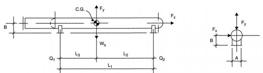 Fx= Kx x Ws
Fy= Ky x Ws
Fz= Kz x Ws
Where:
Ws: Transportation weight.
Kx, Ky, Kz: transport acceleration coefficients. These values must be agreed with the transport subcontractor. As reference values indicated in the following table can be used:
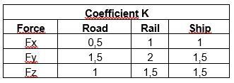 Values obtained from Pressure Vessel Design Manual, D. Moss
 Example of accelerations generated in transported loads. Values obtained from different projects.
Once the loads induced by the mentioned accelerations have been defined, it is necessary to verify the stresses induced on the equipment with the application of these loads. The method used to study these stresses on the shell is the one developed by L.P Zick. The main stresses generated on the shell of the mechanical equipment can be seen in the figure below.
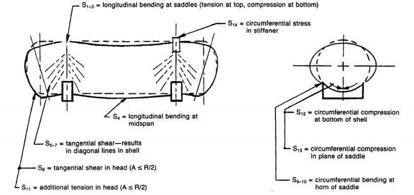 Stresses induced on the shell L.P Zick
As previously indicated, the analysis of the transportation condition of mechanical equipment is a multidisciplinary task that must be defined during the design phase, to avoid future modifications of the equipment or the supporting elements.
If you want to know more: