
Nozzle Loads WRC – FEA
In the design of mechanical equipment, besides the design conditions (pressure and temperature), and the local site conditions (wind and earthquake), the study of local and nozzle loads is of vital importance.
These loads are generated mainly due to way piping systems are supported, alignment and mainly due to the thermal loads generated by the expansion and contraction of the associated line. These thermal movements will intensify the stresses generated in the nozzle, acting in the three main axes. Misalignment between the nozzle and pipe will lead to increased forces and resultant moments.
Normally, the piping designer will create a table of maximum allowable loads at the beginning of each project. When designing the mechanical equipment, the designer must at least ensure that the stresses in the nozzle and equipment wall, resulting from the allowable loads given by the stress-piping department, are within allowable values. Each nozzle shall be able of withstanding the forces and moments under the design conditions of the equipment in the corroded condition.
These studies are mainly carried out according to WRC Bulletin 107/537 & WRC – 297.
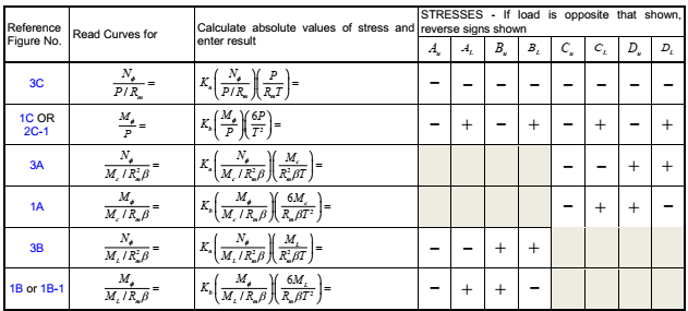
Bulletin WRC 107 published in 1965, analyzes the stresses induced in the nozzle-shell joint. This bulletin can be used in cylindrical and spherical enclosures. The procedure uses parameters obtained from different curves, which allows designers to determine the stresses induced.
In the year 2010 WRC Bulletin 537 was published, this bulletin was issued to facilitate proper interpolation and extrapolation of WRC 107 bulletin, at the same time allowing efficient computation with modern computers.
The following shows the loading conditions in the shell-nozzle joint of a cylindrical shell as per WRC-537:
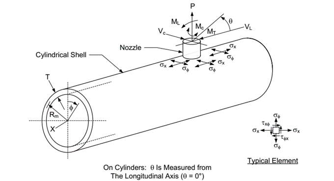
Load conditions in the shell-nozzle joint of a cylindrical shell – WRC 537
Bulletin WRC 297 is a supplement to WRC 107 that was published in 1984, only applicable to cylindrical connections on cylindrical shells. The coverage and applicability of this bulletin is wider than WRC 107, obtaining more reliable results for small d / D values (d: nozzle diameter; D: shell diameter).
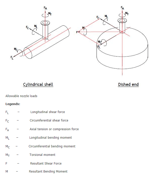
Loads considered in the WRC analysis
When stresses induced exceed allowable ones, it will be necessary to increase the reinforcement of the nozzle, increase the thickness of the shell, or both; so that the values are within allowable stresses.
If this is not feasible due to the fact that the equipment is already manufactured, or it is geometrically not possible to alter the equipment, it will be necessary to act on the design of the piping system to reduce the forces and moments transmitted to the nozzle associated with the equipment.
In those cases where the configuration is outside the geometric limits of bulletins WRC 537 & WRC 297, or when induced stresses are greater than the material allowable stress, it is necessary to resort to finite elements analysis FEA. This analysis allows an evaluation of the induced stresses with great accuracy and level of detail, which is not possible through the mentioned bulletins. There are many tools to perform this analysis to study stresses in the shell-nozzle joint, being the most common FE Pipe, Ansys or SolidWorks Simulation.
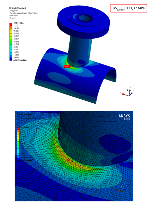
FEA analysis of a nozzle using ANSYS
The following ranges are weak areas in the analysis under WRC, so the use of FEA could be necessary.
- d / D > 0.5
- t / T > 1.0
- values of d / t outside the range 20-100.
- values of D / T outside the range 20-2500.
- d / T < 5.
- Longitudinal connections.
- Temperatures close to creep range.
- Number of cycles greater than 5000.
Being:
D: diameter of the shell.
d: connection diameter
T: thickness of the shell
t: thickness of the shell
If you want to know more:
ASME VIII | Design of Pressure Vessels