Nozzle Design: The Weak Point of All Equipment
- Posted by: César Boró Martín
- Category: Static Equipment
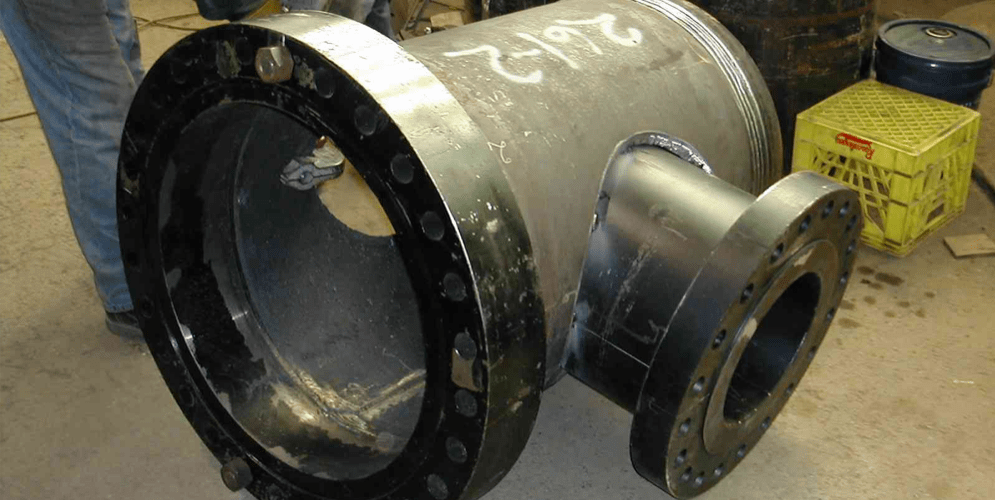
All pressure vessels must be furnished with nozzles and connections. The aim of nozzles is to interconnect the pressure vessel with the rest of the process. The most typical practice to join nozzles and pipelines is to use standard flanges; this ensures a perfect match at assembly and construction stages.
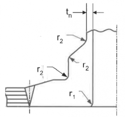
To attach a nozzle in a pressure vessel, it is necessary to make a hole in the shell or head body in question. When making this hole, an area of the vessel is being “taken away”, therefore stress paths are going to divert tangentially to the hole. Thus, we must “substitute” the removed area by adding reinforcement within the limits.
It should be noted that installing a nozzle in a pressure vessel involves a geometric discontinuity that must be taken into account in calculations. Consequently, every method that could be implemented to reduce existing stresses is welcome. One of the most commonly used methods consists in removing stress concentrators by means of rounding sharp edges.
This publication discusses about flanged nozzles that are more susceptible to fluid leakage than welded nozzles. A flanged nozzle consists of the three main elements: flange, neck and reinforcement.
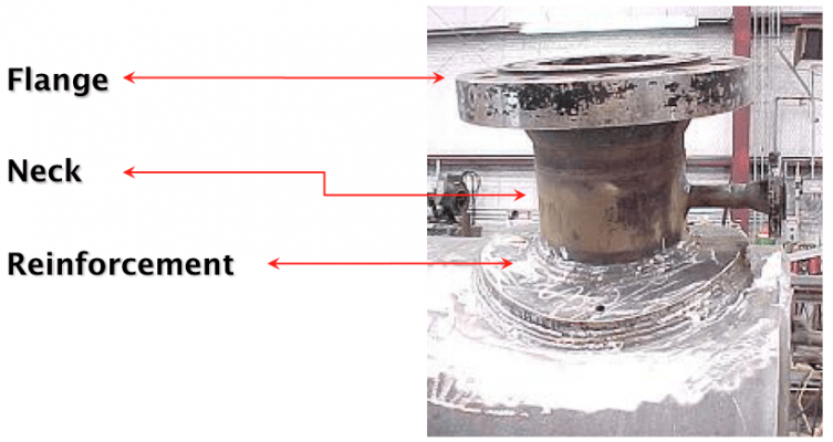 There are different nozzle configurations for pressure vessels as it can be seen in the picture below:
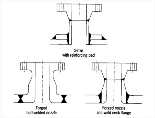
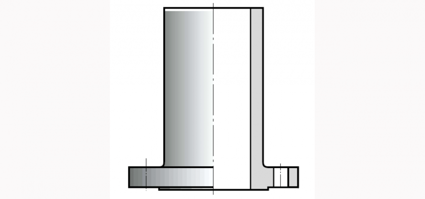
The typical nozzle configuration is with reinforcing plate (or reinforcing pad). In some applications (special, lethal, cyclic, high pressure, high temperature or high thermal gradients services) is recommended to avoid non-integral nozzles configuration, as per ASME Code nomenclature. Consequently, reinforcing pads must be replaced with a self-reinforced nozzle (or forged nozzle). Self-reinforced nozzles could be designed with a variable thickness hub or a straight hub, being the first type a more specific nozzle and therefore more expensive, whilst the second type uses standardized nozzles commonly named as Long Welding Neck. Additionally, if the equipment in under cyclic service and the amount of cycles is high or, even, if there are vibrations affecting the nozzle, a one-piece configuration should be considered, i.e. built-up nozzle would not be acceptable.
If on top of special/lethal services the vessel must be designed for high pressure, it is necessary to design the vessel with safety in mind. For pressure vessel working in critical processes, it is convenient that the weld joint attaching the nozzle to the equipment is as inspected as possible in order to guarantee a safe performance. Due to this, if it is required to radiograph that joint, the nozzle configuration must allow it by means a circumferential lip around the nozzle and a butt weld configuration between both elements must be performed. A particular case of the latter kind is the known as balanced, which has a lip thicker than the pressure vessel part where is attached.
Regardless of the type of reinforcement, there are 2 ways to “attach” the nozzle with the shell/body:
• Set-on: the diameter of the opening in the shell coincides with the inner diameter of the neck. The nozzle is supported by the shell / head.
• Set-in: the diameter of the opening in the shell coincides with the outer diameter of the neck. In this case the nozzle gets through the shell/head.
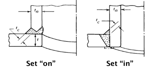
In the first case, the bevel is performed in the nozzle neck, in the second the bevel is performed in the shell or head.
Normally manufacturers are always trying to use Set-on type nozzles: less bevels to prepare and less thickness of weld. On the other hand, customers normally require just the opposite. Usually, Set-on nozzles are permitted by customers when pressure vessel’s thickness is high, when the thickness of nozzle neck is considerably lower than vessel where it will be attached, when no cycles are present in the life of the nozzle and when no special services are considered.
As already mentioned above, when designing nozzles care should be taken regarding maximum loads allowable. These types of nozzles hardly ever fail under external loads; the problem comes with the shell, if this is the case the thickness needs to be increased.
In relation to the type of flanges, it worth mentioning the most common used in the industry of pressure vessels:
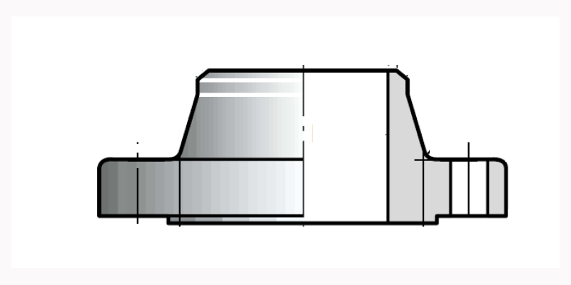
- Welding Neck. The nozzle neck is welded to the flange with a butt weld joint.
- Slip On. This kind of flanges could be accepted only in low critical services (low pressure and temperature, and no special services). In this type, flange and nozzle neck are not welded with a butt-weld joint, but both fillet welds.
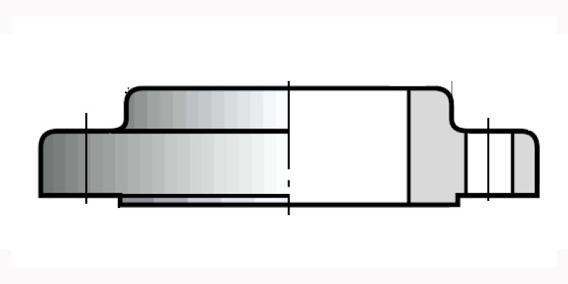
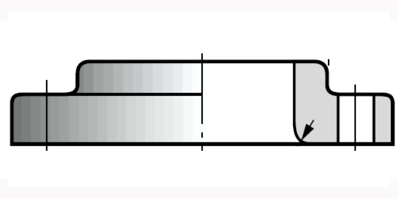
- Lapped. Nozzle neck protrudes the flange and spans it.
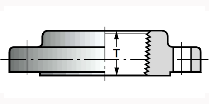
- Threaded. Neck and flange are assembled by means of thread.
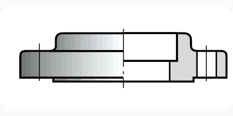
- Socket Welding. The nozzle neck is inserted up to flange limit.
If you want to know more:


 WhatsApp