Design of lifting devices as per ASME BTH-1
- Posted by: datienzae
- Category: Static Equipment Pressure Vessels

ASME BTH-1 Standard – Design of Below the Hook. Lifting Devices, arises after the creation by ASME of a design task group in 1997, to develop a design standard that complements the ASME Code B30.20 Below the Hook. Lifting Devices. Safety Standard, for the design of lifting elements. The standard was published in 2005, consisting of five chapters. The current edition is the 2017 edition in which new chapters and new design categories have been incorporated and new requirements and design elements have been modified and / or added.
ASME BTH-1 provides the minimum structural and mechanical design of the lifting devices, and electrical component selection criteria.
Additionally, lifting devices designed according to this code must also comply with the requirements included in the ASME Code B30.20 – Below the Hook Lifting Devices. Safety Standard. This Code is included in a series of volumes that make up ASME B30, which include the necessary requirements for construction, inspection, installation, testing, and maintenance. The current edition of the ASME B30.20 was published in the year 2018.
ASME BTH-1 standard only refers to provide design requirements. All requirements associated with the safety of the lifting device will be based on ASME B30.20. The designer must work with both codes together when designing the lifting devices of an equipment.
To avoid accidents on site during lifting and / or transportation activities, lifting devices must be designed under the supervision of a qualified and experienced engineer, who verifies the design factors considered in the design phase.
The design requirements evaluated and covered by BTH-1 are the following:
- Classification of the lifting device based on the operating conditions and lifespan of the device.
- Design requirements for the different elements (bolts, pins, welds), as well as recommendations in case of being subjected to fatigue loads.
- Mechanical requirements of the different mechanical components (slings, shackles, accessories).
- Requirements of electrical components.

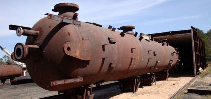
Lifting lugs for pressure vessels
Each lifting device is designated with a design category (strength) and a service class (fatigue conditions). The selection of the design category and the service class will be based on the operating conditions and the expected life of the lifting element, with three design categories (A, B and C) and five different services (service 0 to 4).
The selection of the design category and the service class will define the design requirements of the lifting element, establishing the allowable stresses of the material.
Categories:
- Category A: The magnitude of the load is predictable, and the environmental conditions are not severe. The design factor considered is equal to 2. This category is limited to service classes 0.
- Category B: The magnitude of the load is not predictable in the design and can vary considerably or the environmental conditions can be severe. The design factor in this case is equal to 3. This is the most common design case unless a qualified designer considers the use of category A appropriate.
- Category C: It is used in special applications. The design factor in this case is equal to 6.
Servicies:
The service class associated with the service defines the number of load cycles, or the fatigue life to which the lifting element is designed.

Service Class – ASME BTH-1

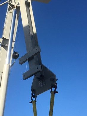
Lifting device with slings and shackle
ASME BTH-1 establishes the design criteria and allowable stress values for the different types of loads to which lifting devices are subjected. The forces to be considered in the analysis include the stresses generated in tension, compression, bending, shear, as well as their combination.
Depending on the lifting device and the conditions during the lifting of the equipment, different stresses will be generated. For example, a lifting beam with a central grip point and a suspended load at the two ends of the beam will be loaded primarily under flexion, so compression and tension calculations will not be predominant.
The study and analysis of all these stresses is developed in section 3 of the ASME BTH-1 Standard. This section corresponding to structural design. Also includes the requirements to be considered for the design of welded joints, evaluating the stresses generated in the joint, depending on its type and geometry.
The fatigue study, in section 3.4 of the standard, is not necessary for lifting devices classified within service class 0 due to the low number of cycles, but as the number of cycles increases, the possibility of fatigue failure also increases.
BTH-1 includes a section that covers how to evaluate lifting devices for service classes 1 through 5.
If you want to know more:


 WhatsApp