Basics of Shell & Tube Heat Exchangers
- Posted by: arvengtraining
- Category: Heat Exchangers

The term heat exchanger encompasses all devices used to transfer energy from one fluid to another. Some examples of this group are: radiators, water heaters, refrigeration batteries, evaporators, steam generators, etc.
Direct contact heat exchangers, also known as mix exchangers, are devices where both fluids undergo a complete physical mixture. On the other hand, devices in which heat transfer takes place through a flat or cylindrical surface are called indirect contact exchangers. There is a barrier that physically separates the two fluid flows, thus there being no possibility of direct contact or contamination between such fluids, except in case of damage of the separation barrier.
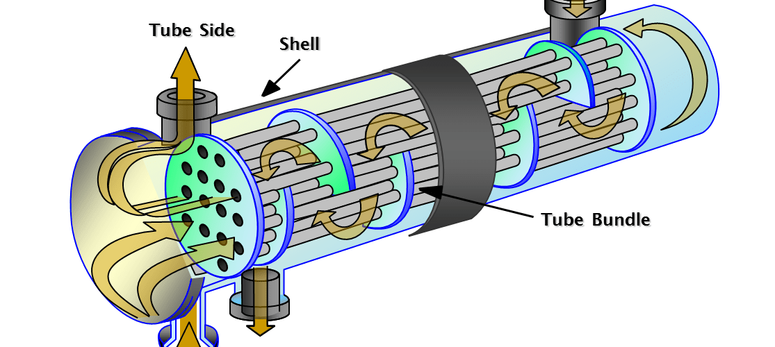
A Shell & Tube heat exchanger is a device in which two fluids, one through the tube side and the other through the shell side, circulating at different temperature conditions, exchange heat through the walls of the tubes, without direct contact between them. These equipment are widely used in chemical process industries, especially in refineries, because of the numerous advantages they offer over other types of heat exchangers, for example:
- The pressures and pressure drops can be varied over a wide range.
- Thermal stresses can be accommodated inexpensively
- There is substantial flexibility regarding materials of construction to accommodate corrosion and other concerns.
- Cleaning and repair are relatively straightforward (easily dismantled)
It is essential for the designer to have a good working knowledge of the mechanical features of S&T heat exchangers, and how they influence the thermal design.
Thermal design
The optimum thermal design of a shell and tube heat exchanger involves the consideration of many interacting design parameters which can be summarised as follows:
- Process fluid assignments to shell side or tube side.
- Selection of stream temperature specifications.
- Setting shell side and tube side pressure drop design limits.
- Selection of heat transfer models and fouling coefficients (shell and tube side).
- Selection of heat exchanger layout and number of passes.
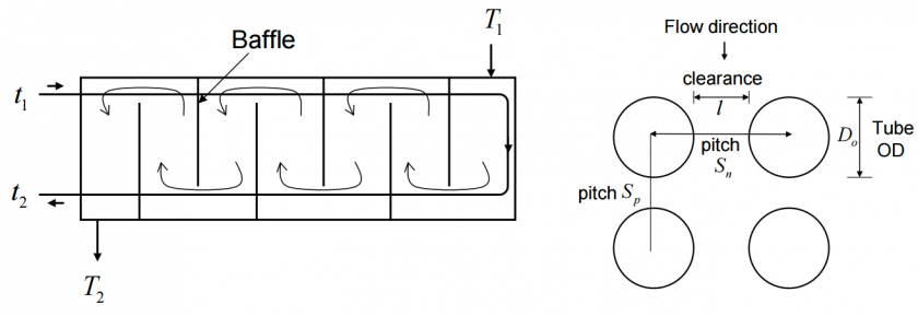
- Specification of tube parameters – size, layout, pitch and material.
- Setting upper and lower design limits on tube length.
- Specification of shell side parameters – materials, baffle cut, baffle spacing, etc.

There are several software design and rating packages available, including AspenBJAC, HTFS and CC-THERM, which enable the designer to study the effects of the many interacting design parameters and achieve an optimum thermal design. It is worth mentioning that software convergence and optimisation routines will not necessarily achieve a practical and economic design without the designer forcing parameters in an intuitive way always bearing in mind sound engineering practices and lessons learned.
If you want to know more:
TEMA | Design of Shell & Tube Heat Exchangers


