


Shell and Tube Heat Exchangers: Types and Technical Differences
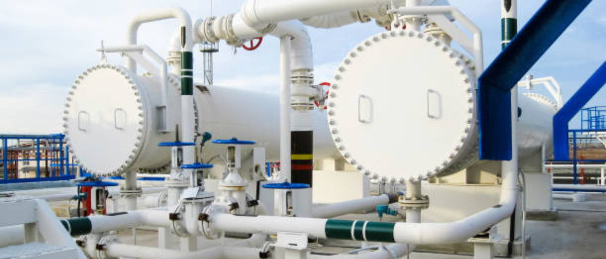
In industrial thermal engineering practice, shell and tube heat exchangers constitute one of the most versatile and widespread pieces of equipment for heat transfer between process streams. Their presence is dominant in refineries, chemical and petrochemical plants, power generation facilities, and numerous continuous process installations.
Based on our experience in design, operations, and technical training, we observe that many equipment selection decisions are made without fully understanding the implications of the chosen construction configuration. However, the choice of exchanger type is not trivial: it directly impacts thermal efficiency, mechanical integrity, maintainability, fouling susceptibility, and, ultimately, the asset’s total cost of ownership.
In this article, we analyze the primary differences between the most common types of shell and tube heat exchangers, linking each configuration to its advantages, limitations, and industrial application fields, consistently aligned with engineering best practices and recognized regulatory references such as the TEMA (Tubular Exchanger Manufacturers Association) standard.
Common Basic Architecture
Before comparing configurations, it is important to remember that all shell and tube heat exchangers share fundamental elements:
-
Tube bundle: A set of tubes through which one of the fluids circulates.
-
Shell: The cylindrical envelope that houses the bundle and conducts the second fluid.
-
Tubesheets: Support and seal the ends of the tubes.
-
Baffles: Guide the flow on the shell side to improve heat transfer and prevent excessive vibration.
-
Headers (channels) and nozzles: Allow for the entry and exit of fluids and facilitate disassembly.
The differences between types arise primarily from how tube-to-shell anchoring is resolved, the compensation for thermal expansion, and the accessibility for cleaning and maintenance.
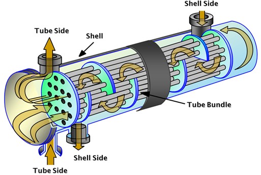
Operating schematic of a shell and tube heat exchanger
Fixed Tubesheet Heat Exchanger
This is the simplest and most economical configuration. Both tubesheets are rigidly welded to the shell, forming a structurally monolithic assembly.
Advantages
-
Lower manufacturing cost.
-
Compact and robust design.
-
Excellent joint tightness.
-
Lower risk of external leakage.
Limitations
-
It does not allow for free differential thermal expansion between the tubes and the shell, unless an expansion joint is installed on the shell.
-
It can generate significant thermal stresses when large temperature differences exist between the fluids.
-
Mechanical cleaning of the shell side is difficult or impossible without complete disassembly.
Typical Applications
We frequently employ this type when:
-
Operating temperatures are moderate.
-
The thermal expansion coefficients of the materials are compatible.
-
The shell-side fluid is relatively clean or does not present high fouling.
From a design perspective, TEMA classifies this type within “BEM” or “BEP” configurations, depending on the type of header (channel) and shell used.
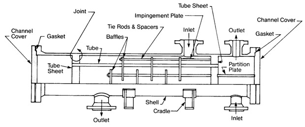
Schematic of a fixed tubesheet heat exchanger
Floating Tubesheet Heat Exchanger
In this configuration, one of the tubesheets is fixed and the other is mobile (floating), allowing the tube bundle to expand freely within the shell.
Advantages
-
Excellent thermal expansion management.
-
Allows for complete bundle extraction for cleaning and inspection.
-
Suitable for high-fouling services.
Limitations
-
Higher manufacturing and maintenance costs.
-
More complex and voluminous design.
-
More potential leak points if not properly maintained.
U-Tube Heat Exchanger
In this design, the tubes are bent into a “U” shape and attached to a single tubesheet. The fluid return occurs within the same tube.
Advantages
-
Eliminates the differential expansion problem.
-
Fewer welded joints.
-
Relatively compact design.
Limitations
-
More complicated internal mechanical cleaning.
-
Difficulty in replacing individual damaged tubes.
-
Not optimal for highly corrosive fluids or those containing solids.
Application Cases
We frequently use them in:
-
Condensing and clean cooling services.
-
Exchangers where the tube-side fluid is relatively clean.
-
Processes where structural simplicity is prioritized over total maintainability.
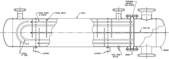
Schematic of a U-tube heat exchanger
“Kettle” Type Exchangers (Reboilers)
This is a special variant within U-tube exchangers. It is the kettle-type exchanger or kettle reboiler, widely used in distillation columns.
Distinctive Characteristics
-
Large volume on the shell side.
-
Well-defined evaporation zone.
-
Controlled vapor outlet toward the column.
Operating Advantages
-
Thermal stability during boiling.
-
Lower risk of liquid entrainment.
-
Efficient control of vapor generation.
Design Considerations
In this equipment, we pay special attention to:
-
Liquid level in the shell.
-
Uniform heat distribution.
-
Corrosion-resistant materials under boiling conditions.
From an applied engineering approach, the main differences between configurations are observed in four key aspects:
Regarding thermal expansion management, floating head and U-tube solutions offer the best adaptation, while fixed tubesheets are less tolerant. Maintainability and cleaning ease is optimal in floating head exchangers, moderate in U-tube designs, and limited in fixed tubesheets. On the other hand, cost and construction simplicity favor fixed tubesheets, while floating heads involve higher investments. Finally, fouling resistance is higher in floating head designs and more critical in U-tubes.
During professional practice, frequent errors are identified that should be avoided: selecting fixed tubesheets without evaluating real thermal stresses, oversizing baffles without analyzing pressure drop, ignoring material compatibility between tubes and shell, neglecting maintenance accessibility from the layout phase, and designing without following TEMA criteria or applicable construction codes.
Applications
Shell and tube heat exchangers are widely used in refineries, petrochemical plants, power generation, and the chemical industry, where they are involved in preheating, condensing, cooling, and reboiling services.
The configuration selection depends on the specific service: fixed tubesheets are typically intended for clean fluids and moderate thermal conditions; floating heads are preferred in services with high thermal expansion or fouling tendencies; U-tubes are suitable for applications where simplicity and good thermal compensation are prioritized; and “kettle” types are common as reboilers in distillation columns.
In all cases, the specific application determines the construction choice and the mechanical and thermal design criteria.
Relationship with Standards and Best Practices
The TEMA standard remains a central reference for classifying, designing, and specifying shell and tube heat exchangers. Additionally, in pressure applications, we typically rely on codes such as ASME Section VIII Div. 1 for structural verification and manufacturing requirements.
The mechanical design, developed according to applicable standards, must guarantee that the equipment meets the thermal requirements of the process. Consequently, the geometric configuration, materials, thicknesses, construction arrangements, and safety margins adopted must be defined in such a way as to ensure the specified thermal performance under operating conditions and throughout the intended service life.
Conclusion
The choice of exchanger type is not simply a construction decision: it is a strategic engineering decision that determines thermal performance, reliability, cost, and maintainability.
From our perspective, there is no universal “best” exchanger. Rather, there is the appropriate configuration for each specific service, considering temperatures, pressures, fluid properties, expected fouling, and the plant’s maintenance philosophy.
A well-founded design—aligned with TEMA, best practices, and operational experience—allows these units to be transformed into reliable and efficient assets within any industrial process facility.