Placement of Condition Monitoring Locations According to API 570
- Posted by: Ricardo Freitas
- Category: Piping

API 570 establishes requirements to maintain the safety and integrity of piping systems already in service. This code is not a substitute that replaces the original design code used for the development of the piping systems. It defines in-service inspection procedures, line condition monitoring, repair, and maintenance, ensuring accurate and timely evaluations to ensure operation within minimum acceptable limits. It covers metal piping systems, fiberglass reinforced plastic (FRP), and pressure relief devices. Polymeric pipes made of homogeneous materials, such as high- and low-density polyethylene, polypropylene, among others, are not included.
Planning and Development of Pipe Inspection
To maintain the safety and integrity of piping systems already in service, it is essential to have an inspection plan.

The frequency and scope of inspections are based on the types of degradation most likely to occur in the systems and the consequences that may lead to failure. An inspection plan is first developed taking into account the scope, frequency, techniques, and location of inspection.
This plan uses analysis of historically collected data and methodologically collected inspection records to evaluate the mechanisms of potential damage, thereby determining the methods and extent of non-destructive examination (NDE) that will be needed to adequately identify and evaluate the severity of the potential damage.

Minimum contents that the inspection plan must have
- Types of inspection needed and next inspection date.
- Description of scope and locations of NDE inspection in CML, inspection methods and NDE techniques to be applied, surface cleaning mechanisms for each type of inspection, pressure tests, any previous repairs before the next inspection, types of anticipated damage to piping systems that may occur, location of expected damage, and any special access in the areas to be monitored.
Placement of Condition Monitoring Locations
These points are specifically selected along the route of a pipe circuit to carry out the corresponding inspections and evaluate the current state of the pipe, usually compared to its recorded history.

Establishing CMLs is essential to monitor corrosion, erosion, wear, and other changes in the condition of pipelines that could compromise their integrity and operational safety. Based on the measurements obtained at these points, informed decisions are made about the maintenance, repairs, or replacements needed to ensure the safe and efficient operation of the pipes that make up the systems.
Properly selecting locations for CMLs and performing regular inspections are key components of an API 570 pipeline integrity program. Each CML must identify potential damage mechanisms, such as localized corrosion and any other degradation mechanisms of the material. The different aspects that are monitored in CMLs include wall thickness, stress cracking, corrosion under insulation (CUI) and high temperature hydrogen attack among others.
Area surveillance (CML)
Each piping system is unique and requires proper monitoring using CML. Areas with high rates of widespread corrosion or localized corrosion generally require more CMLs and a higher frequency of monitoring.
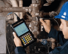
Detection of minimal thickness in a CML can be performed by ultrasonic scanning (UT) or radiographic profile (RT). In addition, electromagnetic (MT) techniques are also useful for identifying areas of material loss, which can then be measured in detail using UT or radiography (RT).
For each CML, it is essential to record the lowest thickness reading or an average of several readings from measurements taken within the area examined. This data is crucial for calculating corrosion rates, determining remaining service life, and planning the next inspection. Measurements to be made in selected areas of the systems should cover each of the four quadrants of the pipe and fittings, with special attention to the inside and outside radius of elbows and tees, where corrosion or erosion could increase the rate of deterioration due to the fluid-dynamic condition that may occur there.
The rate of corrosion/erosion or damage is calculated from successive historical measurements and using this information, the interval of the next inspection cycle is determined. It is essential to calculate corrosion rates and remaining useful life to identify the limiting component of each pipe circuit, using statistical analysis as indicated by API 570. In addition, it is essential to consider risk areas such as continuous insulation (CUI), soil-air interfaces (SAI), and areas near changes in pipe material or specifications. These analyses help identify both localized and generalized and uniform corrosion, adjusting inspection and maintenance strategies.
CMLs should be marked on inspection drawings, allowing for repetitive measurements at consistent locations in the piping system over the life of the system. Recording these points provides accurate data to calculate the annualized corrosion rate. This rate, determined from successive measurements, allows the next inspection interval to be established based on the remaining useful life or through RBI analysis.
Area Mapping (CML)
In the refining and petrochemical industries, corrosive processes tend to be relatively uniform, resulting in a constant rate of wall reduction anywhere in the pipeline circuit, whether axial or circumferential. In such cases, fewer CMLs will be needed to monitor a circuit compared to systems subject to more localized corrosion. Theoretically, a circuit with uniform corrosion could be monitored with a single CML. However, in practice, corrosion is rarely completely uniform and can be quite localized, requiring multiple CMLs. Inspectors must use their knowledge, and that of their team, to optimize the placement of CML in each circuit, balancing the data collection effort with the benefits obtained.
If there is well-supported and recorded historical data of sufficient thicknesses for a circuit and these have been validated as representative of the expected corrosion environment, it is possible to perform a statistical analysis. This analysis helps determine the necessary number of inspection points to establish the desired confidence in the calculation of the average corrosion rate, the limiting thickness, and/or the remaining life of the circuit.
A greater number of CML areas should be selected for corrosive piping systems with the following characteristics:
- Greater potential for environmental or safety emergency in the event of a leak
- High expected or experienced corrosion rate
- Greater potential for localized corrosion
- Greater complexity in terms of accessories, branches, dead sections, injection points, and similar elements
- Greater potential for CUI
- Greater variability of corrosion rate
- Greater degree of variability in the process (process parameters that will affect localized corrosion)
- Circuits in corrosive environments that have experienced unexpected failures in the facility or elsewhere in the industry
Fewer CMLs can be selected for piping systems with any of the following characteristics:
- Low potential for environmental or safety emergency in the event of a leak
- Relatively non-corrosive piping systems
- Long, essentially straight piping systems
Finally, CMLs can be eliminated for piping systems with any of the following characteristics:
- Extremely low potential for environmental or safety emergency in the event of a leak
- Non-corrosive systems, as demonstrated by history or similar service
- Systems not subject to changes that could cause corrosion as demonstrated by history and/or periodic reviews
For more information:


