Non-standard flanges – ASME VIII
- Posted by: arvengtraining
- Category: Piping Static Equipment

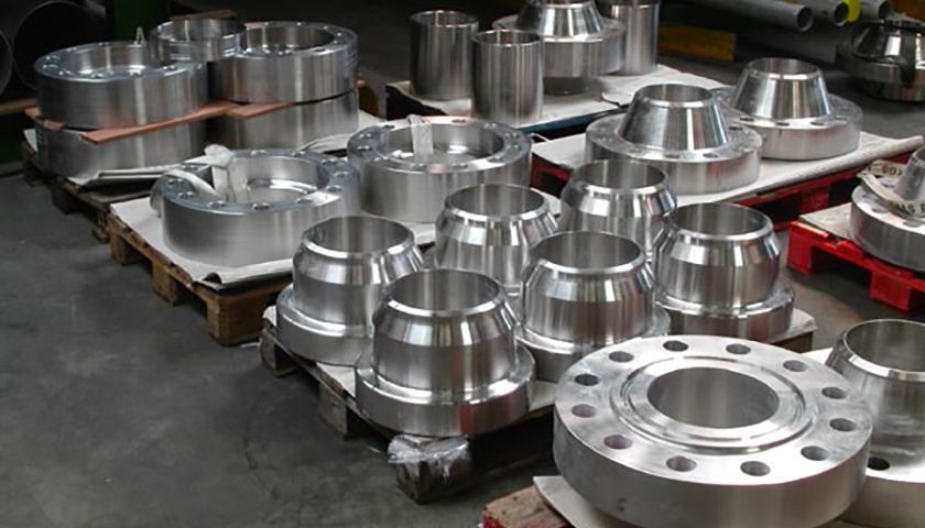
Non-standard flanges will only be used in cases where pressure, temperature and size requirements exceed the capabilities of standard flanges. Keep in mind that non-standard flanges require calculation, design and special manufacturing procedures, which is why they are chosen only as a last resort. The most common such applications are large equipment flanges and heat exchangers body flanges.
Non-standard flanges are designed and calculated according to ASME VIII Div.1 Appendix 2 and Appendix S, and according to ASME VIII Div.2 part 4.16.
Design criteria
Rules for the design of bolted flange connections as described in Div.1 Appendix 2 apply to flanges with gaskets placed entirely within the circle enclosed by the bolt holes and with no contact outside this circle.
This method is applicable to circular flanges under internal pressure and takes into account only hydrostatic end loads and gasket seating loads. Rules have been further modified so that they can be applied to the design of flanges under external pressure, reverse flanges and flanges with nut stops.
Design procedure for large diameter, low pressure flanges shall be supplemented by methods other than the code e.g.: check flange rotation. Flanges greater than 60 inches (1524 millimeters) inside diameter and designed for up to 100 psig (689 KPa) pressure fall under this category.
Design of flanges involves the selection of the following:
- Flange Material
- Bolting Material
- Gasket Material and type
- Type of facing (RF, M and F, T and G, RJ, etc.)
- Hub proportions
Load definition
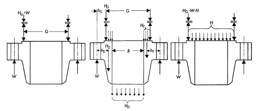
In the design of a bolted flange connection, calculations shall be made for each of the two design conditions: operation and gasket seating, the more severe shall control.

1) Gasket seating
The gasket seating load is defined under the conditions existing when the gasket or joint-contact surface is seated by applying an initial load, with the bolts assembling the joint – at room temperature and atmospheric pressure.
The minimum initial load considered to be adequate for proper seating is a function of the gasket material and the effective gasket or seating area.
2) Operating condition
Conditions required to resist the hydrostatic end force of the design pressure tending to part the joint, and to maintain sufficient compression on the gasket to assure a tight joint at all times.
The minimum load is a function of the design pressure, the gasket material and the effective contact area of the gasket.
If you want to know more:


 WhatsApp