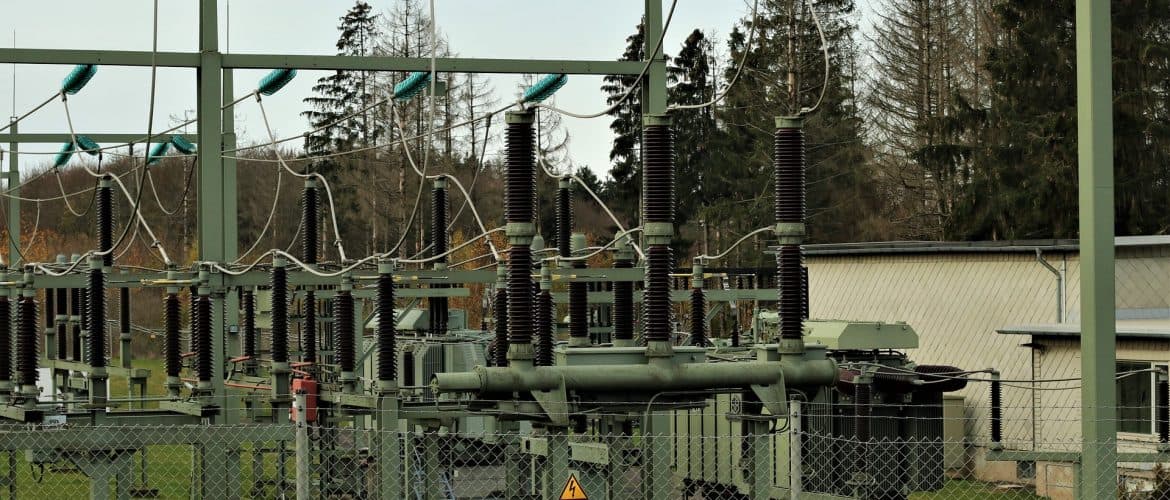
Electrical equipment distribution in a substation
- Posted by: Martín Torres
- Category: Electrical Engineering

The physical distribution of equipment in the substation is a study that demands much information and dedication. Typically, equipment is distributed in the electrical room under certain guidelines, such as:
- The switching devices that power or receive power from the transformers are located on the wall, on the yard side of the transformers. In this way, access to the bus or cable ducts will have the shortest route possible and their installation will not cross above (or below) all the substation equipment.
- The MCCs are usually distributed in such a way that the supplies coming from the SWGs are as short as possible, since the cables between these equipments are usually of a high section and a large amount of cable per phase. The same is true in case busbars are used to interconnect SWGs and MCCs. It is also important to have defined in which area of the substation the cables will leave towards the field loads. Remember that the number of cables leaving the MCCs to the field is usually large and routing through the trays becomes critical. This often establishes a pattern of priority location of the MCCs, over the criteria of locating them near the SWGs.
- Equipment such as MCCs, variable speed drives, among others, can only be accessed from the front or front and rear. This will determine whether they can be installed back to back, saving space in the substation, or whether they must be installed individually to be able to access from both sides.
- The UPS and battery chargers, and their distribution panels, should be located near the battery rooms to reduce distances from the cables connecting them.
- Variable speed drives and/or soft starters must be installed between the SWG or MCCs powering them and the substation cable outlet to the field.
- Auxiliary distribution panels (lighting, outlets, space heaters, miscellaneous loads, etc.) and their auxiliary transformers (when required) are tipically installed against the wall as they do not usually require rear access and thus save space in the substation.
- Electrical control system or switchboard of UPS and battery charger cabs, being critical equipment, are usually installed outside the arc flash boundary (arc flash boundary).
The free space needed between the boxes will often depends on the requirements of each client and the type of box. For example, in front of medium voltage SWGs and MCCs, is usually required.a space of 1.5/2 meters. This is due to the fact that the depth of the cabins, and extractable carts of these equipment, usually require this space for their extraction and operation. Equipment such as SWG and low voltage MCC usually require around 1 mt free in front on their sides. It is necessary to be careful and to clearly establish with the client whether these distances are being taken into account with the cabin doors open or closed (usually it is with the second option). These spaces are required not only for maintenance, but also to provide an unobstructed emergency exit in the event of an emergency.. Additionally, in the event that maintenance is required to the panel or future expansion, it must be considered that in these spaces the equipment can move towards the exit doors without being blocked inside the substation.
Another important consideration in the design of a substation is the space required to accommodate future extensions of both transformers in the yard and equipment (mainly SWGs and MCCs) inside the equipment room. It is always better to design the building with space for extensions of the electrical system than to have to build a second building to accommodate the extensions.
[1] The arc flash boundary is the minimum “safe” distance from exposed energized conductors or circuit parts that has the potential for an arc flash.
For more information:


 WhatsApp