Differences between PFD’s and P&ID’s
- Posted by: Esteban Pulgar
- Category: Process Engineering

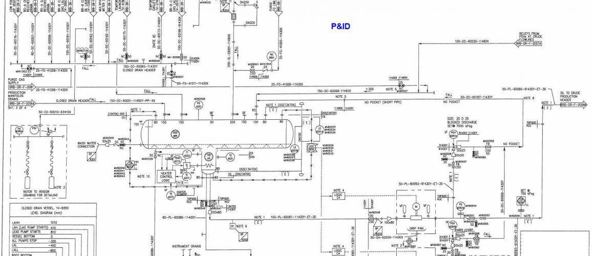
Piping and Instrumentation Diagrams (P&ID’s) can often be confused with Process Flow Diagrams (PFD’s). P&IDs and PFDs generally use the same notation for teams. However, they serve different purposes and provide different information. The purpose of a PFD is to show exactly what a process does during operation, and a P&ID shows all the controllers, valve types, and materials used in construction. A PFD shows the connectivity and relationships between the main equipment and units of a process. However, it also includes tabulated design values such as normal, minimum, and maximum operating conditions which a P&ID does not contain. A PFD does not include minor piping systems or other minor components that a P&ID normally includes.
The difference between P&IDs and PFDs is that P&IDs typically include more information about piping, control, and safety relief valves than process flow diagrams. P&IDs do not contain operational specifications that PFDs do, such as flows and stream compositions. It should be noted that the differences between PFD and P&ID will vary among different plants. Most plants maintain designated standards for creating and modifying these documents. Both PFDs and P&IDs are controlled documents and must be maintained with a document control procedure.
The following information is provided in a P&ID that is not explicit in a PFD:
- ALL valves and valve types.
- Controllers present
- Controller architectures
- Pipe diameters, materials of construction and insulation properties (including minor piping systems)
- Equipment construction materials.
A P&ID is developed based on information from the process flow diagram (PFD), which is developed based on a block flow diagram (BFD). However, P&ID development is not limited to passing the information from the PFD to the P&ID. A PFD only covers the main elements of a plant. There are several other elements in a plant that do not appear on a PFD (such as sampling points, bypasses, mechanical valves, relief devices, etc.).
Because the development of the P&ID starts from the PFD, the symbols and text information in the PFD must be transferred to the P&ID, but this transformation is not a blind act. Symbols and text information must be converted to their corresponding symbols and text data in the P&ID.

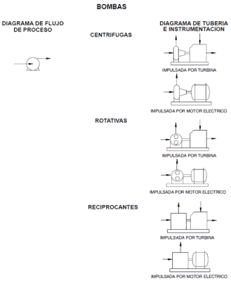
Representation of pumps in PFD’s Vs P&ID’s.
On a PFD, we see a single symbol as a process step, where such a symbol is reminiscent of the concept of pumps. On some PFDs, there is only one symbol for different types of pumps, including centrifugal or positive displacement (and this can be confusing for those unfamiliar with a PFD). When we display a bomb symbol on a PFD, we are essentially saying, “liquid must be transferred from point A to point B, by an unknown type of pump that will become clearer later in the P&ID.” A pump symbol on a PFD just shows “something to transfer liquid from point A to point B”. Each symbol on a PFD has a general meaning and does not refer to any specific type of that equipment.
The other aspect of the PFD concept is that a line does not necessarily represent pipes; They only represent flows. This means that one line on a PFD could actually represent two (or more) pipes going to two (or more) parallel units.

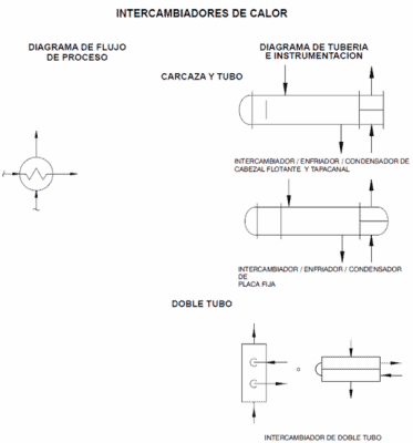
Representation of Heat Exchangers in PFD’s Vs P&ID’s.
Therefore, the most intensive activity during P&ID development is deciding on the type of equipment. A general symbol for a heat exchanger on a PFD should be replaced with a specific symbol for shell and tube heat exchanger, plate and frame, or the other types of heat exchangers when transferred to the P&ID. Sometimes the type of process elements is decided when sizing is done, but at other times this decision is left to the P&ID developers. This activity is commonly overlooked because in many cases P&ID development begins with a set of P&IDs rather than blank sheets.
For more information:


 WhatsApp