ASME PCC-1: Determination of the target torque of bolted joints – Simple method
- Posted by: Ricardo Freitas
- Category: Piping Static Equipment

Determining the magnitude of the tightening torque to be applied to a stud or screw in a flanged joint is very important to ensure that a joint seats correctly and is maintained under different conditions, thus achieving what is desired: avoiding leaks. This always taking into account that no permissible value of any component that constitutes this type of union is exceeded.
Therefore, the purpose of defining the target torque is to find the appropriate tension in the bolts and that this is adequately transmitted to the assembly to achieve the correct assembly, considering the total integrity of all its components and finally that of the joint as a watertight element.
There are two approaches to setting the Target Torque through the use of this code:
• Simple approach
• Joint component approach
The main distinction between the single approach and the joint approach to calculating the bolted joint torque lies in the level of precision and technical rigor applied in the calculation. While the simple approach is based on reference tables with typical torque values and in many cases simplifying some variables to allow results that are sometimes conservative and with a faster response, the joint approach is completer and more detailed, considering a larger number of wide range of variables, incorporating more precise equations and models to determine the required torque based on the specific characteristics of the bolted joint. The joint approach takes into account very important aspects such as the uniform distribution of the load, the relationship between the quality of the lubrication on the clamping element and the result in the coefficient of friction, the precise sequence of tightening, the tolerances and the different mechanisms that are used, thus ensuring a safe and reliable installation in critical industrial applications, where mechanical integrity and precision are of vital importance.
The use of a single common bolt stress across all flange sizes and ratings, for example 345 MPa, can result in a stress at the joint that does not provide adequate margin to deal with:
• Creep
• Relaxation
• Application of external loads
• Variation due to thermal loads
• Other
The use of a possible higher tension in the bolts can cause the bolts to be loaded beyond their elastic limit, causing possible unwanted permanent deformations in various components of the assembly.
Precautions
• Under the guidelines of the ASME PCC-1 code, it is considered that, for the joint components to be within acceptable limits, the following must be verified:
• The surface finish
• The spacing of the bolts
• The rigidity
• The good condition of the bolts
• The characteristics of the materials and the application temperatures
• Gaskets experience a reasonable amount of relaxation during the initial stage of operation (>15%) i.e., gasket relaxation will exceed any operational increase in bolt load.
• Bolt stress limits should be verified at maximum operating and ambient temperature.
• The methodology is for ductile materials, unit strain at break due to traction greater than 15% (ε).
• For brittle materials the bolt stress and component failure point can be greatly reduced, additional safety factors are required.
• The method does not consider the effect of fatigue, creep, or media attack damage mechanisms around the bolt or flange.
• To consider the above cases, additional reductions in assembly bolt stress may be required to prevent possible failure.
Definitions, parameters and variables to determine the Target Torque in ASME PCC-1
 Selecting the Bolt Mounting Target Stress – Simple Method
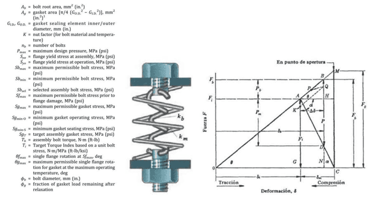
For the simple approach, it is recommended to consider as a minimum the target joint stress “SgT”, for each type of joint.
Determination of the adequate tension for the stud or bolt, can be determined according to:
𝑺𝒃𝒔𝒆𝒍 = 𝑺𝒈𝑻 ∗ 𝑨𝒈/(𝒏𝒃 ∗ 𝑨𝒃)
Sbsel= Selected assembly stress
The average stress for the bolts in each joint can be selected, and this value can be converted into a torque table using the following equation:
𝑻𝒃 = 𝑆𝑏𝑠𝑒𝑙 ∗ 𝐾 ∗ 𝐴𝑏 ∗ ∅𝑏/1000; Metric units
𝑻𝒃 = 𝑆𝑏𝑠𝑒𝑙 ∗ 𝐾 ∗ 𝐴𝑏 ∗ ∅𝑏/12; English units
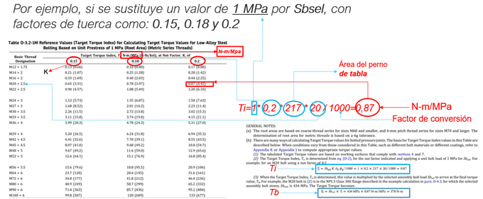
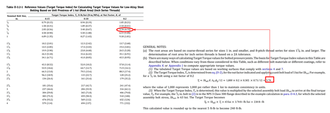
Alternatively, tables O-3.2-1M and 0-3.2-1 tabulate the target torque ratings, “Ti”, based on the above equations using a bolt tension unit (for example, substituting a value of 1 for Sbel =1), with nut factors at 0.15, 0.18 and 0.2.

The final tightening torque of the mounting bolt for English units.

Some considerations regarding the tables to obtain the “Target Torque Index, Ti”
• Nut factors (K) provided in the previous tables represent examples and may vary from actual values. “K” is a dimensionless parameter that is determined experimentally and is related to the coefficient of friction.
• The value of “K” at room temperature is generally considered to be approximately the coefficient of friction plus 0.04. Therefore, for the development of the previous tables, the coefficients of friction of 0.16 and 0.12 correspond approximately to nut factors of 0.20 and 0.16

• Experimental “K” factors for nuts are available from various sources. Special care must be taken to ensure that the factors are applicable to our consideration.
• The “K” factor for SA-193 low alloy steel bolts varies between 16 to 0.23 at room temperature
• It is worth noting the load sensitivity obtained to an applied torque from relatively small changes in the nut factor:
For example, a change in “K” between 0.1 to 0.3 does not result in a 20% change in torque, but rather a 200% change.
Insufficient application of lubricant to working surfaces will have the effect of adding significant variability to the bolt load.
• Recent research has shown that the “K” nut factor depends on:
• The bolt material
• The diameter of the bolt
• The assembly temperature
These factors can be significant and should not be ignored when selecting the “K” nut factor. It is advisable to look for the results of the tests carried out with bolts and similar anti-seize specifications or to carry out nut factor tests (size and material) with your own conditions and even more so when you are in the presence of critical system joints.
• Nut factor “K” tests can be performed relatively easily by tightening a bolt to a given torque and measuring the bolt load obtained, either by calibrated ultrasonic measurement, using a calibrated load cell, or by measuring the pressure rise in a hydraulic tensioner.
Reference
• “An Introduction to the Design and Behavior of Bolted Joints,” Bickford, p. 233.
• ln test results, the effect of temperature was found to halve the nut factor over the ambient temperature range often found in the field [0°C to 40°C (32°Fto 100°F)] for one anti-seize product. In addition, the nut factor has been found to increase by 30% with SA-193 B8M bolts, by comparison to SA-193 B7 bolt material tests.
For more information:


 WhatsApp