
Vibration in Piping Systems
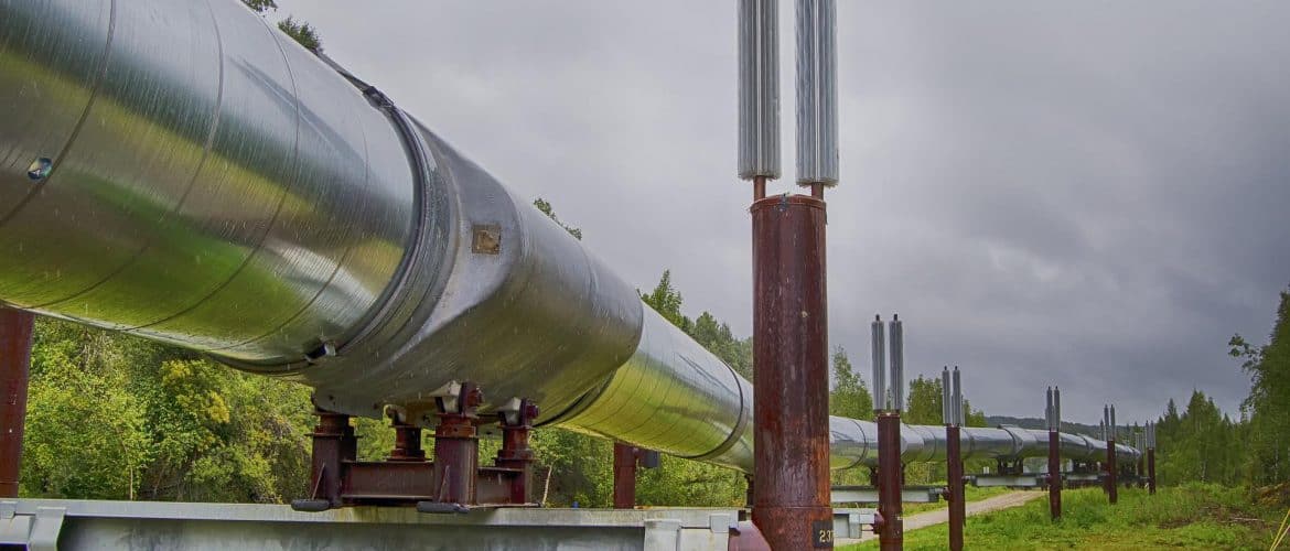
Vibration is one of the major causes of failure in piping systems connected to turbomachinery equipment. Piping systems are subjected to excessive vibration levels whenever the mechanical natural frequency of the system is excited by a pulsation or by a mechanical source.
If the frequency of the load excitation is the same or in the neighborhood of the mechanical natural frequency of the piping network system, a strong resonance will occur.
Natural frequency and mode shapes are dynamic properties of the structure. They are controlled by the mass and stiffness of the system. The natural frequency and mode shapes describe the tendency of the structure to vibrate when subjected to dynamic loading.
Natural frequencies and mode shapes of a structure are determined by modal analysis. They are computed starting from the mode with the lowest frequency. The lowest natural frequency is called the fundamental natural frequency.
Since only the modes with lower frequencies get a significant response to the source of excitation, only modes with lower frequencies are calculated for the analysis.
Natural frequency is defined as the number of vibration cycles per unit of time. For straight uniform runs of pipe, the natural frequency can be calculated as follows:
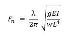
where,
Fn – pipe span natural frequency
λ – frequency factor
g – gravitational acceleration
E – modulus of elasticity
I – moment of inertia
L – span length
w – weight per unit length of pipe, fluid service and insulation if applicable
For piping spans with uniformly distributed mass and a concentrated load, the fundamental natural frequency can be computed with the following equation:

where,
Fw – fundamental natural frequency of the pipe span with concentrated mass
Fn – natural frequency of the pipe span without concentrated mass
M – total uniformly distributed mass of pipe span
P – concentrated load
C – correction factor
There is a variety of piping vibration sources. Typical excitation sources that can lead to large vibrations in piping systems are:
- Pulsation caused by reciprocating centrifugal pumps and compressors
- Mechanical energy from turbomachinery unbalanced moments and forces
- Pulsations generated by pressure surge/momentum changes due to valve operations
- Flow-induced vibrations (FIV)
- Acoustic induced vibration (AIV)
- Pulsations induced by cavitation and flashing phenomena
Pulsations that occur in fluid-filled piping systems are basically pressure fluctuations that travel at the speed of sound through the piping system. The speed of sound depends on the bulk modulus of the fluid, material, diameter, and thickness of the pipe.
The pulsation characteristics of piping systems depend on the properties of the pumped fluid service, piping layout, number of pumps, operational speeds, pump type, pump power and system operating conditions.
Flow-induced vibrations are typically caused by fluid flow discontinuities that occur at tees, reducers, at short or mitered bends and at partially closed valves. Flow induced vibration excites the low-frequency regions of the pipe (range of 0 Hz – 100 Hz). This type of vibration causes the pipe to displace in the longitudinal and transversal directions.
Acoustically induced vibration is a phenomenon characterized by intense acoustic pressures caused by large pressure drop that occurs in pressure-reducing devices such as orifice plates, pressure relief valves, control valves and blow-down valves. Acoustic induced vibration excites the high-frequency regions of the pipe (range of 500 Hz – 2,500 Hz). This vibration type causes the pipe to displace in the circumferential direction.
Vibrations can lead to cavitation in suction lines, loosen threaded connections, fatigue cracks at pipe fittings, at welded pipe supports, leaks at flanges, broken or lose pipe clamps, valve failures, reduced pump hydraulic performance and degradation of the efficiency of the system.
Solutions to mitigate the effects of the excessive vibrations in piping systems include the following basic guidelines:
- Minimize the number of bends installed in the piping system
- Concentrated weights shall be rigidly supported with pipe clamps
- Piping supports shall be installed on each side of bends and at all piping discontinuities
- Lower pipe span between supports to raise the mechanical natural frequencies
- Increase the stiffness of the system by increasing the pipe thickness
- Increasing pipe diameter one or two sizes reduces the flow velocity in the pipe which can prevent the occurrence of vibration
- Guides with clearance gaps employed to allow for thermal expansion shall not be used to mitigate vibration in pipes
- Use of sway braces limits the effects of piping vibrations
- The natural frequency of the piping system should be above the highest excitation frequency by a factor of two
- The stiffness of supports and clamps should be twice the pipe span stiffness
- Threaded connections for instrumentation and small-bore lines are prone to vibration failures at thread roots
- Small bore piping shall be braced to the main pipe in order to reduce the relative vibrations between the small-bore lines and the main pipe
- Use of pulsation control devices such as dampeners, acoustic filters, accumulators, hydraulic isolators, dampers, and orifice plates
If you want to know more: