Heater tune-up
The Air and Fire Draft Regulation Diagram (DRAFT diagram for short), shown in the following figure, is a practical tool for controlling draft and excess oxygen in process heaters.
This diagram, based on Figure 19 (Natural Draft Heater Adjustment Chart) of the API RP 535 standard, more explicitly clarifies the application of single actions (with the damper or with the air registers) as opposed to double actions, that is, those in which the opening of the damper or registers must necessarily be followed by a closing action of the alternative device.
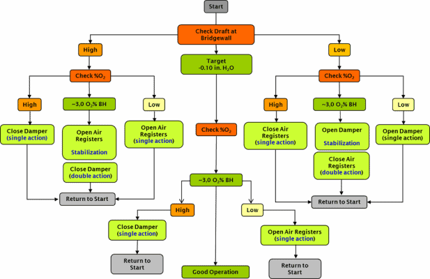
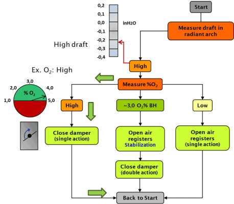
Since the draft evaluation recorded a value of -0.22 inH2O, the console operator in the Control Room must proceed according to the indications in the left sector of the diagram, corresponding to a high draft. Additionally, the oxygen analyzer indicated 4.7% excess oxygen on a wet basis, which also implies a high value.
Step 1
Based on the DRAFT diagram, the operator’s action should be to close the stack damper, from the control console. The field operator must verify, on-site, that the arrow indicating the damper opening has effectively moved in the expected direction.
Step 2
The next step should then be to wait prudently until the operational variables have responded adequately to the change made and the heater has stabilized. Then, as indicated in the DRAFT diagram, the heater evaluator must go back to the start and measure the draft again.
Now suppose that the operating conditions of the heater stabilize, although maintaining the draft indications still slightly higher than the value defined as the goal (-0.10 inH2O) but that the oxygen level in the gases is within the desired range. In this case, the flow diagram indications continue to be those of the left sector (high draft), although now the excess oxygen does correspond to the desired value (~ 3.0% BH). These conditions are illustrated in the diagram below.
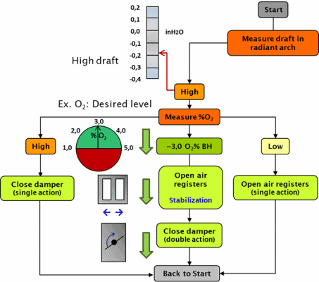
The operational goal of reducing draft has not yet been achieved. So, could the damper be closed again to achieve this?
Certainly, it could be done, but it would be counterproductive to operate in this way since it would run the risk of disproportionately reducing the air intake and causing such a deficiency that it would imply incomplete combustion of the fuel with the added risk of producing flame flashbacks (a.k.a. delayed combustion or post-combustion), generating smoke in the stack or a high concentration of carbon monoxide in the gases…
Step 3
For these reasons, the diagram establishes a double action as a precaution, that is, first opening the air registers to guarantee the combustion process, even if this implies a slight increase in the oxygen concentration in the gases, and later, once the oven is stabilized, closing the damper, which in addition to reducing the draft, will also return the oxygen value to the desired levels.
A final verification of the operation of this heater may indicate full compliance with the operational goals for draft and excess oxygen.
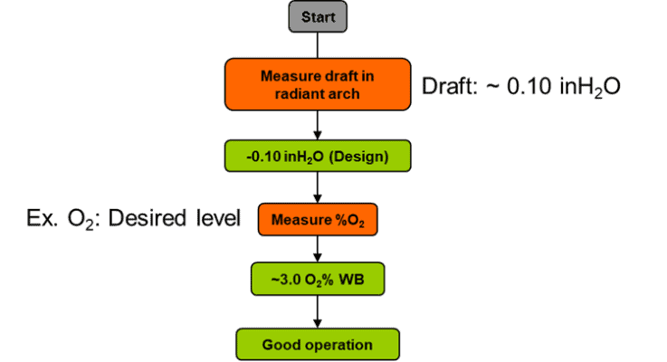
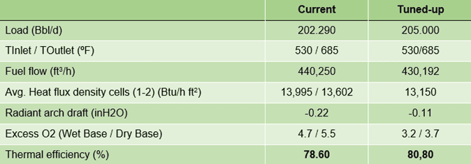
As excess air decreases, less energy is used to heat the air stream and more energy is transferred to the process fluid. When the furnace control detects an increase in fluid temperature, it will automatically reduce fuel consumption.
Energy savings in a refinery furnace are obtained primarily by reducing heat losses associated with combustion gases and excess air by reducing air flow and stack gas temperatures.
The correct operation of the heater, measured as a function of draft and excess oxygen, has as an immediate consequence the reduction of fuel consumption and the average heat flux density in the radiant section and with it the proportional increase in thermal efficiency.
If you want to know more:



 WhatsApp