The selection, design, and location of piping supports is an essential part in the study of any industrial process installation.
Typically, piping is supported at regular intervals on steel supports embedded in concrete foundations or directly on steel structures. The distance between supports is the span.
The allowable spans between supports of horizontal lines are mainly limited by the longitudinal forces that must be kept within limits, or, in some cases, by the maximum deflection. Similarly, in other special cases, the span can be limited to control the natural frequency of the pipe, so as to avoid undesirable vibrations.
One of the reasons it is important to control deflection is to avoid forming air pockets. However, the most important reason deflection is limited is to ensure that the system has sufficient rigidity to avoid vibration.
In a horizontal, simple, open field line, the spacing of supports depends only on the strength of the pipe material. Within the limits of a process unit, the support spacing is determined mainly by the spacing of conveniently located columns.
The locations of piping supports are dependent upon four factors: pipe size, piping configuration, locations of valves and fittings, and any structures that are available capable of providing support.
Commonly, the spacing or section between frames of a piperack will be determined based on the weakest pipe. Small diameter lines can be propped up by providing intermediate supports; attached to the larger adjacent pipe; or a group of such lines can also be supported together so that their combined inertia increases.
Sometimes, however, the most practical solution is simply to increase the diameter of the pipe to the point that it is self-supporting along the required span.
Maximum distance between supports
The maximum recommended space between supports can be established by two methods: either by calculating the maximum distance the pipe can span according to its bending stress and deflection, or through tables in codes and project/client specifications.
a) Allowable stress and deflection
For straight sections of pipe without concentrated weights such as valves and other heavy fittings, the maximum span between supports is based on the bending stress when the pipe is operating with the heaviest fluid (normal operations or hydrotest).
The calculation is made using the classical mechanics equations for a simply supported beam, where the maximum span will be the lowest value obtained from calculating both the stress and maximum deflection:
 Allowable Stress Maximum deflection
Where:
L = maximum span between supports [mm]
Z = Pipe section modulus [cm3]
Sadm = allowable stress [kPa]
W = Total weight per length unit [kG/m]
E = Pipe elasticity modulus [kPa]
I = Moment of Inertia of the pipe [cm4]
∆adm = allowable deflection [mm]
b) Code tables and specifications
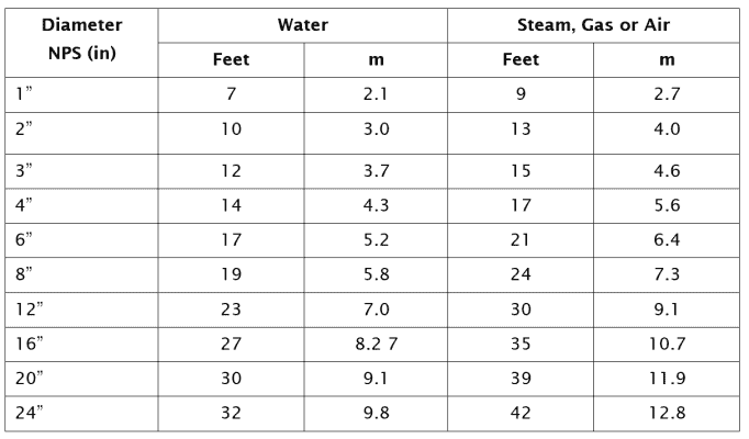
In some projects, it is a common practice to have more stringent requirements than the maximum span calculated in the previous section. These are often based on conservative criteria in terms of allowable stresses in pipe. In these cases, the maximum span is tabulated, and it can be found in the following format:

(ASME B-31.1 TABLE 121.1.4 SUGGESTED PIPE SUPPORT SPACING)
Notes:
- Maximum spacing between horizontal supports and SCH STD and upper, operating at a maximum temperature of 400º C.
- Spacing not applicable when there are concentrated loads between supports, for example: flanges, valves, etc.
- The spacing is based assuming a beam with a bending stress that does not exceed 15.9 Mpa and insulated pipe. In addition to a permitted deflection of 2.5 mm between supports.
Support location in the piping system
Once the piping routing is well defined, the lines can be analysed for support requirements. When drawings of structures and equipment are available, supports can be selected and located.

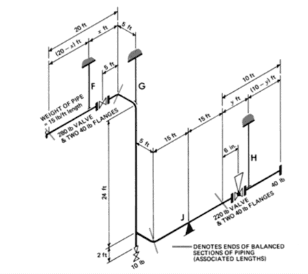
Example of supports location.
The two fundamental criteria for obtaining an economical design for supports are:
- Grouping the lines to minimize the number of structures required.
- Keeping the lines as close as possible to the support points, either in existing structures or at ground level.
The criteria to be adopted when supporting a group of piping systems (e.g. a piperack), will depend on the process requirements and on the economics of the system.
Ideally, each support would be associated with the centre of gravity of a pipe of a certain length. If this criterion could be maintained in the entire piping system, it would eliminate torsional moments.
However, the presence of valves, flanges and other fittings of considerable weight, determine the new centre of gravity.. The designer must be able to section the system into subsystems and analyse them through the considerations and equations of classical mechanics, static and material resistance.
Usually, the points where the anchors should be placed are determined first, then the simple supports and finally the guides and the braces.
The proper location of hangers or fixed supports requires information about the pipe, the structure to which the load is transmitted to and space limitations. The preferred points for the location of supports are:
- On the pipe itself and not on components such as valves, fittings or expansion joints.
- On straight sections of the pipe instead of on elbows, angular joints or connections of prefabricated branches, since in these places the system is already subjected to highly localized stresses..
- On sections of the pipe that do not require frequent removal for cleaning or maintenance.
- As close as possible to large load concentrations.
A piping system is perfectly supported when the anchors provide sufficient restriction to thermal expansions and the supports and guides are correctly located to support the sustained loads.
Anchors restrict the movement of the pipe; deflections and rotations are prevented with guides and stops. Braces are used when required to stiffen the system due to occasional loads; these stiffen the pipe and prevent vibrations.
If you want to know more:


 WhatsApp