


Pipe Interconnection To Equipment In Industrial Plants
In the design of industrial plant piping interconnection, the proper integration between pieces of equipment is one of the most critical and complex tasks faced by piping engineers. It not only directly impacts operational efficiency, but also has a significant influence on construction, maintenance, and safety costs.
The Importance of Piping Interconnection Design in Industrial Plants
In process facilities such as refineries or petrochemical complexes, piping accounts for approximately 50% of engineering work-hours, 35% of material cost, and 30% of field labor cost. Poor design can significantly increase construction costs and compromise plant operability.
Plant layout and equipment arrangement must consider factors such as maintenance,
safety, quality, constructability, and cost-efficiency. The piping designer plays a key role in this process, collaborating with multiple disciplines to ensure a functional and efficient design.
Piping Interconnection Design in Shell and Tube Heat Exchangers
Piping interconnection in these units must ensure counterflow circulation of fluids: normally, cold fluid enters from the bottom and exits at the top, while the hot fluid follows the reverse path. This configuration facilitates vapor removal and enhances thermal efficiency. Nevertheless, other configurations are also valid as long as they meet the process requirements.
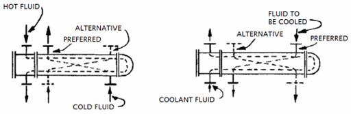
Connection alternatives for S&T heat exchangers
In stacked exchangers, nozzles should be positioned as close as possible to minimize thermal expansion stresses. Clearance in front of the channel and distributor must be maintained to allow for maintenance.
Air Coolers: Efficiency vs. Flexibility
Air coolers are typically installed on structures near the equipment they serve, optimizing thermal efficiency and pressure drop but limiting system flexibility. Piping designers generally cannot relocate equipment nozzles, meaning the piping arrangement must adapt to the equipment configuration.
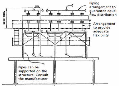
Interconnections of an air cooler
Piping must be properly supported and sufficiently flexible to prevent loads on equipment nozzles exceeding the manufacturer’s allowable values. In general, no piping should run above the air cooler that would obstruct the removal of the tube bundle.
Unlike shell and tube exchangers, air coolers have no removable parts, influencing maintenance strategies.
Centrifugal Pumps: The NPSH Challenge
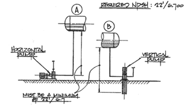
Interconnection to a centrifugal pump
One of the greatest challenges in pump interconnection design is ensuring adequate Net Positive Suction Head (NPSH). The pump requires a minimum suction head for satisfactory operation, which is controlled primarily by the elevation of the source equipment. While there are several ways to increase available suction head, raising the source equipment elevation is the most effective and economical.
The primary objective when locating a pump is to minimize suction piping length while meeting flexibility and nozzle load requirements.
Pumps must be installed with adequate clearance (minimum 750 mm) for maintenance. Where a pipe rack is available, pumps are often placed below the pipe rack. Suction lines should be short, free of pockets, and designed to avoid cavitation risks. Piping should not pass above pumps, and congestion in front of pumps should be avoided to facilitate maintenance.
Compressors: Accessibility and Vibration
Compressor interconnection design must ensure maintenance access, particularly if vehicle access is required. Suction lines should be short and straight to reduce costs and energy consumption (long suction lines increase required drive power).
Centrifugal and rotary compressors have fewer vibration issues than reciprocating ones but still require proper support. Direction changes in compressor piping should be minimized, flow disturbances avoided, and nozzle loads mitigated with flexible supports or expansion joints.
Auxiliary service connections such as cooling water, lubrication oil, auxiliary steam, and balance gases must also be considered. Check valves should be installed close to compressor nozzles to prevent backflow.
Piping Interconnection Design in Pressure Vessels: Simplicity and Coordination
Pressure vessel interconnection is comparatively straightforward but demands close collaboration between piping design, process, and vessel fabrication teams. Vessel height is often dictated by NPSH requirements, potentially leading to frequent redesigns.
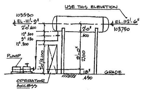
Height of pressure vessels
Instrumentation connections should be located away from turbulence zones, and piping must allow for support installation without excessive load transmission. In vertical vessels, clearance for personnel access must be maintained.
In fractionation towers, grouping piping can simplify support design and connection to the pipe rack. Nozzle orientation, trays, ladders, platforms, and manways should be carefully planned.
Instrumentation: Precision in Design
Instrumentation is vital for process control. Control valves, flowmeters, and thermocouples should be installed per manufacturer recommendations to ensure accurate measurement.
Instrument panels should occupy minimal space while allowing maintenance without process interruption. In temperature measurements for mixed streams, a minimum straight length before the thermometer should be provided to ensure reliable readings.
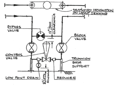
Regulator Panel Setup
Conclusion
Piping interconnection design in industrial plants demands precision, interdisciplinary coordination, and deep technical expertise. Each equipment type presents unique challenges that must be addressed with efficiency, safety, and maintainability in mind. Proper piping layout not only optimizes plant performance, but also reduces costs and enhances operational safety.
For more information:
ASME B31 | Design of Piping Systems for Industrial Plants